Local Variables

Let's move on to the code at $203D. It starts by storing a couple of values into zero page addresses $02/03. This appears to be setting up a pointer to $2063, which is a data area inside the file. So let's make it official.
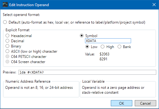
Select the line at address $2063, and use Actions > Edit Label to give it the label "XDATA?". The question mark on the end is there to remind us that we're not entirely sure what this is. Now edit the operand on line $203D, and set it to the symbol "XDATA", with the part "low". The question mark isn't really part of the label, so you don't need to type it here.

Edit the operand on line $2041,
and set it to "XDATA" with the part "high". (The symbol text box
gets focus immediately, so you can start typing the symbol name as soon
as the dialog opens; you don't need to click around first.) If all
went well, the operands should now read LDA #<XDATA?
and LDA #>XDATA?.
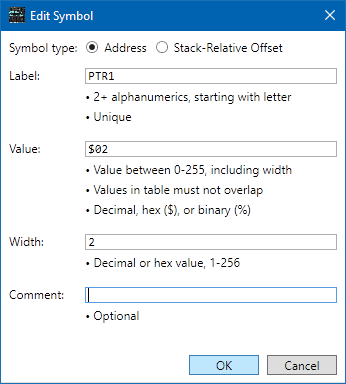
Let's give the pointer a name. Select line $203D, and use Actions > Create Local Variable Table to create an empty table. Click New Symbol on the right side. Leave the Address button selected. Set the Label field to "PTR1", the Value field to "$02", and the width to "2" (it's a 2-byte pointer). Click "OK" to create the entry, and then "OK" to update the table.

There's now a .VAR statement
(similar to a .EQU) above line $203D,
and the stores to $02/$03 have changed to
"PTR1" and "PTR1+1".

Double-click on the JSR opcode on line $2045 to jump
way down to L20A7.
The code here just loads a value from $3000 into the accumulator
and returns, so not much to see here. Hit the back-arrow in the
toolbar to jump back to the JSR.
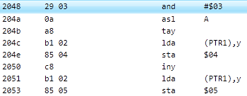
The next bit of code masks the accumulator so it holds a value between
0 and 3, then doubles it and uses it as an index into PTR1.
We know PTR1 points to XDATA,
which looks like it has some 16-bit addresses. The
values loaded are stored in two more zero-page locations, $04-05.
Let's make these a pointer as well.
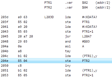
Double-click the operand on line $204E ("$04"),
and click Create Local Variable. Set the Label
to "PTR2" and the width to 2. Click OK
to create the symbol, then OK
to close the operand editor, which should still be set to Default format --
we didn't actually edit the operand, we just used the operand edit
dialog as a convenient way to create a local variable table entry. All
accesses to $04/$05 now use PTR2, and there's a new entry in the local
variable table we created earlier.
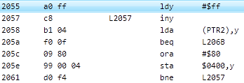
The next section of code, at $2055, copies bytes from PTR2
to $0400, stopping when it hits a zero byte.
It looks like this is copying null-terminated strings.
This confirms our idea that XDATA holds 16-bit addresses,
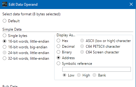
so let's format it. Select lines $2063 to $2066 (the latter of
which continues through $206A), then
Actions > Edit Operand.
The editor window should say "8 bytes selected" at the top.
Click the 16-bit words, little-endian radio button,
and then in the Display As box, click Address.
Click OK.

The values at XDATA should now be four
.DD2 16-bit addresses.
If you scroll up, you'll see that the .ZSTR strings
near the top now have labels that match the operands in XDATA.
Now that we know what XDATA holds, let's rename it.
Change the label to STRADDR. The symbol parts in the
operands at $203D and $2041 update automatically.
Showing Cycle Counts
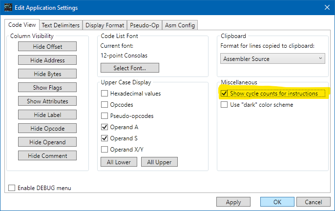
Let's take a quick look at the cycle-count feature. Use Edit > Settings to open the app settings panel. In the Miscellaneous group on the right side, click the Show cycle counts for instructions checkbox, then click OK. (There's also a toolbar button that toggles it on and off.)

Every line with an instruction now has a cycle count on it. The cycle
counts are adjusted for everything SourceGen can figure out. For example,
the BEQ on line $205A shows "2+" cycles, meaning that
it takes at least two cycles but might take more. That's because
conditional branches take an
extra cycle if the branch is taken. The BNE on line
$2061 shows 3 cycles, because we know that the branch is always
taken and doesn't cross a page boundary.
(If you want to see why it's always taken,
look at the value of the 'Z' flag in the "flags" column, which indicates
the state of the flags before the instruction on that line is executed.
Lower-case 'z' means the zero-flag is clear (0), upper-case 'Z' means it's
set (1). The analyzer determined that the flag was clear for instructions
following the BEQ because we're on the branch-not-taken path.
The following instruction, ORA #$80, cleared the 'Z' flag and
set the 'N' flag, so a BMI would also be an always-taken branch.)
The cycle-count comments can be added to generated source code as well,
with an application setting in the Asm Config tab.
If you add an end-of-line comment, it appears after the cycle count. (Try it.)